



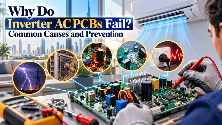
Inverter AC PCB Failure: Final Troubleshooting Guide
Inverter AC PCB Failure is one of the most expensive problems owners can face in a modern air conditioner. Unlike conventional AC systems that rely on relatively simple on-and-off compressor control, inverter air conditioners use sophisticated electronic boards to regulate compressor speed, fan operation, voltage conversion, sensors and communication between indoor and outdoor units.
- What Does an Inverter AC PCB Actually Do?
- Common Causes of Inverter AC PCB Failure at a Glance
- Voltage Fluctuation Is One of the Biggest Risks
- Power Surges Can Damage a PCB Almost Instantly
- Overheating Can Destroy Inverter Power Modules
- Moisture and Condensation Can Corrode Electronic Boards
- A Faulty Compressor Can Destroy a New PCB
- Loose Wires and Poor Connections Create Hidden Damage
- Poor Grounding Can Increase Electrical Risk
- Dust and Dirty Outdoor Units Can Indirectly Damage the PCB
- Frequent Power On and Off Can Stress the Inverter Circuit
- Insects and Small Animals Can Short-Circuit PCB Components
- Ageing Components Can Eventually Cause PCB Failure
- Warning Signs of an Inverter AC PCB Problem
- How Technicians Diagnose Inverter AC PCB Failure
- Should an Inverter AC PCB Be Repaired or Replaced?
- How to Prevent Inverter AC PCB Failure
- Preventive Maintenance Checklist for Inverter AC Owners
- Common Mistakes That Lead to Repeat PCB Failure
- Inverter AC PCB Failure: Final Troubleshooting Guide
The PCB, or printed circuit board, acts as the electronic control centre of the system. In an inverter AC, the outdoor PCB may also include high-power electronic components such as rectifiers, capacitors, insulated-gate bipolar transistors and intelligent power modules that convert incoming electricity into the controlled power required by the variable-speed compressor.
Because these components operate under electrical, thermal and environmental stress, several different problems can eventually cause damage. Manufacturer service documentation shows that inverter-board faults can be linked with overcurrent, overheating, low voltage, damaged compressors, loose wiring and failures within the power electronics themselves. LG service manuals, for example, list inverter PCB and IPM faults associated with compressor overcurrent, IPM overheating, poor terminal connections and abnormal power conditions.
The good news is that not every PCB failure is unavoidable. Stable power, proper installation, regular servicing, clean outdoor units and early attention to unusual operating symptoms can reduce the risk significantly.
What Does an Inverter AC PCB Actually Do?
The PCB in an inverter air conditioner performs far more work than a simple control board.
A conventional fixed-speed AC generally switches the compressor on and off depending on the room temperature. An inverter model instead changes compressor speed continuously so that cooling output can match the actual requirement.
To achieve this, the electronic system has to manage multiple functions at the same time.
These can include:
- Compressor speed control
- Indoor fan control
- Outdoor fan control
- Temperature sensors
- Refrigerant-pressure protection
- Communication between indoor and outdoor units
- Voltage conversion
- Current monitoring
- Error detection
- Safety shutdowns
The outdoor inverter PCB is particularly important because it controls the high-power side of the system.
Incoming AC electricity is typically converted into DC and then switched electronically to create the variable-frequency power needed by the compressor motor.
This means the PCB is exposed to both mains electricity and substantial heat.
A failure in a small component can therefore stop the entire air conditioner even when the compressor, fan and refrigerant circuit are otherwise functional.
Common Causes of Inverter AC PCB Failure at a Glance
PCB failures rarely happen for one reason alone. Electrical stress, heat and environmental exposure can work together over time.
| Cause | How It Can Damage the PCB | Risk Level |
|---|---|---|
| Voltage fluctuation | Stresses capacitors and power electronics | High |
| Power surge | Can instantly damage semiconductor components | High |
| Overheating | Shortens component life and can damage IPM/IGBT modules | High |
| Moisture | Causes corrosion, leakage current and short circuits | High |
| Loose connections | Creates unstable voltage and excessive heat | Medium–High |
| Compressor fault | Can create excessive current through inverter stage | High |
| Dust and blocked airflow | Raises PCB and heat-sink temperature | Medium |
| Frequent power cycling | Stresses inrush and power components | Medium |
| Poor installation | Can create wiring and grounding problems | Medium–High |
| Component ageing | Capacitors and relays deteriorate over time | Medium |
| Insects or rodents | Can create short circuits or physical damage | Medium |
| Improper repair | Can damage tracks, connectors or components | High |
Understanding these causes helps technicians diagnose the real problem rather than simply replacing the PCB and hoping the failure does not return.
Voltage Fluctuation Is One of the Biggest Risks
Inverter AC electronics depend heavily on stable input power.
When supply voltage repeatedly rises above or falls below the expected operating range, the power electronics inside the PCB have to work under additional stress.
LG India advises users to check supply voltage when an air conditioner experiences operating problems and gives an expected operating range of approximately 200–240V for the models covered by its consumer troubleshooting guidance.
In manufacturer service documentation, abnormal input voltage and poor power connections are also listed as possible causes of inverter DC-link and PCB faults.
Voltage problems can affect components such as:
- Capacitors
- Bridge rectifiers
- Switching transistors
- Voltage regulators
- Power modules
- Control ICs
Low voltage is not harmless simply because it appears less dramatic than a surge.
If the system attempts to maintain compressor output while supply conditions are poor, current can rise and place extra stress on electronic components.
Repeated fluctuations can eventually weaken components even if the air conditioner continues operating initially.
Power Surges Can Damage a PCB Almost Instantly
A strong surge is different from normal voltage fluctuation.
It is a short-duration increase in voltage that may occur because of:
- Lightning
- Grid switching
- Transformer disturbances
- Large electrical equipment
- Restoration of electricity after an outage
Electronic semiconductor components can be sensitive to these sudden voltage spikes.
Panasonic’s industrial electronics guidance notes that excessive surge voltage can cause malfunction or permanent damage in solid-state electronic components, which illustrates why surge suppression is widely used in power-electronic systems.
An inverter AC PCB may contain some internal protection, but protection has limits.
A sufficiently strong surge can damage:
- Metal oxide varistors
- Fuses
- Rectifier circuits
- Power modules
- Microcontrollers
- Communication circuits
Sometimes the protective component sacrifices itself and prevents wider damage.
In other cases, several components fail together.
This is why a PCB that appears “burnt” after a storm or sudden power restoration may actually be showing the result of an electrical surge rather than an internal manufacturing defect.
Overheating Can Destroy Inverter Power Modules
Heat is one of the biggest enemies of electronics.
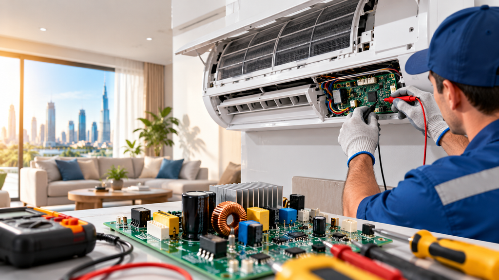
The outdoor inverter board contains components that handle significant current, and these components generate heat during normal operation.
Manufacturers therefore use heat sinks and cooling arrangements to move heat away from power modules.
LG service documentation specifically lists IPM overheating as a cause of inverter PCB faults and tells technicians to check whether the heat sink is correctly attached.
If heat cannot escape properly, semiconductor junction temperatures rise.
Over time this can damage the module.
Possible causes of PCB overheating include:
- Dirty outdoor coil
- Blocked outdoor airflow
- Faulty outdoor fan
- Poorly attached heat sink
- Deteriorated thermal compound
- Excessive ambient temperature
- Continuous overload
In very hot climates, outdoor AC electronics already operate in challenging conditions.
That makes airflow and maintenance especially important.
A unit placed in an enclosed balcony or poorly ventilated utility area may experience much higher temperatures than one installed in a suitable outdoor location.
Moisture and Condensation Can Corrode Electronic Boards
Water and electronics are a dangerous combination.
Outdoor AC units are designed to operate in exposed environments, but the electronic compartment must still remain protected from direct water entry and excessive condensation.
Moisture can cause:
- Corrosion
- Electrical leakage
- Short circuits
- Connector damage
- Copper-track deterioration
Panasonic’s electronics guidance notes that condensation can contribute to insulation deterioration and component failure.
In AC systems, moisture exposure can occur because of:
- Heavy rain entering an incorrectly installed unit
- Pressure washing
- Condensation
- Poor enclosure sealing
- Drainage problems
- High humidity
A technician may initially see only green or white corrosion around connectors.
Over time, however, corrosion can spread underneath components or damage fine PCB tracks.
This is particularly difficult because the board may operate intermittently before failing completely.
A Faulty Compressor Can Destroy a New PCB
One of the most important diagnostic mistakes is assuming every inverter error means the PCB itself is the original problem.
The compressor can cause the PCB to fail.
The inverter board supplies controlled three-phase power to the compressor. If the compressor has damaged windings, insulation failure or an internal mechanical problem, it may draw excessive current.
LG service manuals specifically list compressor damage and compressor overcurrent among the causes technicians should investigate when diagnosing inverter PCB/IPM faults.
This is critical when replacing an expensive PCB.
If the technician installs a new board without checking the compressor first, the replacement board may fail again.
Before replacing an inverter PCB, technicians commonly need to verify:
| Check | Why It Matters |
|---|---|
| Compressor winding resistance | Detects abnormal winding conditions |
| Insulation resistance | Helps identify leakage to ground |
| U-V-W terminals | Confirms correct connections |
| Compressor current | Detects excessive load |
| DC link | Confirms correct inverter supply |
| Heat sink | Confirms adequate cooling |
Manufacturer troubleshooting procedures similarly instruct service technicians to check compressor resistance, insulation and wiring before condemning the PCB.
Loose Wires and Poor Connections Create Hidden Damage
Loose electrical connections can create serious problems even though they may initially look harmless.
When a connector is loose, electrical resistance increases at the contact point.
This can produce heat.
The connection may also become intermittent, causing voltage fluctuations or arcing.
LG service documentation lists disconnected or loose compressor terminals and abnormal wiring among the possible causes associated with inverter PCB protection faults.
Common problem areas include:
- Main power terminals
- Compressor U-V-W connections
- DC-link connectors
- PCB plug connectors
- Neutral wiring
- Earth connections
A terminal that was not tightened correctly during installation may work normally for months before vibration and heat make the connection worse.
This is why installation quality matters so much with inverter air conditioners.
A good technician should inspect connectors and terminal torque rather than focusing only on refrigerant pressure.
Poor Grounding Can Increase Electrical Risk
Grounding is an important safety and equipment-protection measure.
An AC system that is not properly earthed can behave unpredictably during electrical faults or surges.
Poor grounding may contribute to:
- Electrical shock risk
- Communication instability
- Surge damage
- Unwanted voltage on the chassis
- Electronic malfunction
Grounding should follow the manufacturer’s installation instructions and local electrical regulations.
Adding improvised earth wires or connecting the unit to unsuitable metal structures is not a substitute for proper electrical grounding.
For an inverter AC, grounding becomes particularly important because the system contains switching electronics that operate at high frequency.
Correct wiring and earthing help the electrical protection system work as intended.
Dust and Dirty Outdoor Units Can Indirectly Damage the PCB
Dust does not always damage the PCB directly.
More often, it creates thermal problems.
When the condenser coil becomes clogged, the outdoor unit cannot release heat efficiently.
The compressor and power electronics then operate under higher thermal stress.
Daikin advises users to keep air inlets and outlets free of obstruction and to maintain clean filters because blocked airflow can interfere with normal operation.
For an inverter PCB, restricted cooling may raise the temperature of:
- IPM modules
- IGBTs
- Rectifiers
- Capacitors
- Heat sinks
Heavy dust inside the electrical compartment can also absorb moisture.
That combination may increase the risk of leakage current and corrosion.
In dusty environments, regular maintenance is therefore important not only for cooling performance but also for electronic reliability.
Frequent Power On and Off Can Stress the Inverter Circuit
Repeatedly switching the AC off and immediately back on is not good practice.
Power electronics experience high charging current when the DC-link capacitors first energise.
Manufacturers design systems to tolerate normal starts, but unnecessary rapid cycling creates additional electrical and thermal stress.
Mitsubishi Electric’s inverter guidance specifically warns that repeated frequent power ON/OFF can overheat or damage inrush-current-limiting circuitry.
Modern air conditioners often include restart delays to protect the compressor and electronics.
Users should allow those protective delays to work rather than repeatedly turning the breaker or isolator on and off.
This is especially relevant after a power outage.
If supply is unstable, repeatedly trying to restart the air conditioner can expose the electronics to additional stress.
Insects and Small Animals Can Short-Circuit PCB Components
This cause sounds unusual, but technicians regularly encounter it.
Small insects can enter the outdoor-unit electrical compartment and move across exposed electronic areas.
If an insect bridges two high-voltage points, it can cause a short circuit.
Geckos, lizards and rodents can also create problems in some regions.
Possible damage includes:
- Shorted tracks
- Burnt components
- Damaged wiring
- Contaminated connectors
The correct solution is not to spray pesticides directly onto the PCB.
Chemical sprays can leave conductive or corrosive residues.
The better approach is to ensure the electrical enclosure is properly closed and that cable entry points remain correctly sealed without blocking necessary ventilation.
Ageing Components Can Eventually Cause PCB Failure
Electronic components do not last forever.
Electrolytic capacitors are particularly sensitive to age and heat.
Over time, they can lose capacitance, develop higher internal resistance or fail completely.
Other components can also deteriorate, including:
- Relays
- Solder joints
- Connectors
- Power modules
- Varistors
Heat accelerates many ageing processes.
This is one reason an inverter AC that has operated in extreme outdoor temperatures for many years may eventually develop electronic faults even when it has been properly maintained.
Age-related failure does not necessarily indicate poor quality.
Every electronic system has a finite operating life.
The goal of preventive maintenance is to reduce unnecessary stress so components have the best chance of reaching their expected service life.
Warning Signs of an Inverter AC PCB Problem
PCB faults can produce many different symptoms.
However, these symptoms are not proof that the board is damaged because compressor, sensor and wiring faults can create similar behaviour.
Common warning signs include:
| Symptom | Possible Cause |
|---|---|
| AC does not start | PCB, power supply or communication problem |
| Outdoor unit does not run | PCB, compressor or sensor fault |
| Error code appears repeatedly | Electronic or system protection condition |
| Compressor starts and stops | Power, PCB or compressor problem |
| Breaker trips | Short circuit, compressor or PCB fault |
| Burning smell | Overheated wiring or electronic component |
| Outdoor unit works intermittently | Heat, connector or PCB issue |
| Cooling varies suddenly | Sensor, refrigerant or inverter-control problem |
| PCB fuse keeps blowing | Downstream short or PCB failure |
A technician should diagnose the entire system before replacing the board.
Simply seeing an error code and ordering a new PCB can lead to an expensive misdiagnosis.
How Technicians Diagnose Inverter AC PCB Failure
Proper diagnosis follows a sequence.
The exact method depends on the manufacturer and model, but the goal is to determine whether the PCB failed independently or because another component damaged it.
A typical diagnostic process may include:
- Read the error code.
- Check supply voltage.
- Inspect fuses and visible components.
- Check terminal connections.
- Test compressor winding resistance.
- Test compressor insulation resistance.
- Check fan motor.
- Inspect DC-link voltage.
- Inspect heat-sink condition.
- Confirm communication wiring.
LG’s troubleshooting flow for inverter PCB/IPM faults follows a similar logic, instructing technicians to check power wiring, compressor resistance and insulation, compressor connections, DC-link wiring and heat-sink condition before replacing the PCB.
This systematic approach helps prevent repeat failures.
Should an Inverter AC PCB Be Repaired or Replaced?
PCB repair is possible in some situations.
However, whether repair is appropriate depends heavily on the type of damage.
PCB repair may be practical when:
- One identifiable component has failed
- Tracks can be restored reliably
- The board is not badly burnt
- Replacement board is unavailable
- A qualified electronics technician performs the work
Replacement may be safer when:
- The IPM is extensively damaged
- Multiple power components have failed
- PCB layers are carbonised
- Moisture corrosion is widespread
- Manufacturer requires complete assembly replacement
- Reliability is critical
One challenge with board-level repair is hidden damage.
A surge that destroys one visible component may also weaken several others.
The repaired board may work temporarily and fail again later.
Authorised service centres frequently replace the complete PCB assembly because this provides a more predictable repair outcome.
How to Prevent Inverter AC PCB Failure
Not every failure can be prevented, but several practical steps can reduce risk.
Use stable electrical supply
If the property experiences frequent voltage problems, have the electrical system checked by a qualified electrician.
Depending on the installation and manufacturer requirements, appropriate surge protection or voltage-protection equipment may also be considered.
Maintain airflow
Keep the outdoor coil and ventilation paths clean.
A dirty outdoor unit increases operating temperatures and places additional stress on both the compressor and power electronics.
Avoid rapid power cycling
Allow the AC’s built-in restart delay to work.
Do not repeatedly switch the breaker on and off.
Service electrical connections
Periodic maintenance should include inspection of terminals, connectors and signs of overheating.
Protect against moisture
Avoid directing high-pressure water at the electrical compartment during cleaning.
Investigate compressor faults
If the inverter repeatedly reports overcurrent or IPM errors, the compressor should be checked before replacing the board.
Preventive Maintenance Checklist for Inverter AC Owners
A simple maintenance routine can improve both cooling performance and electronic reliability.
| Maintenance Item | Suggested Action |
|---|---|
| Indoor filter | Clean regularly |
| Outdoor coil | Keep free of dust and blockage |
| Outdoor airflow | Ensure ventilation is not restricted |
| Electrical terminals | Inspect during professional service |
| Supply voltage | Investigate repeated abnormal readings |
| Surge protection | Consider where electrical supply is unstable |
| Drainage | Keep water away from electrical sections |
| Error codes | Diagnose rather than repeatedly resetting |
| Compressor | Test when overcurrent faults appear |
| PCB compartment | Keep clean and dry |
Homeowners should avoid opening the inverter PCB compartment themselves.
Even after power is disconnected, high-voltage capacitors can retain a dangerous electrical charge.
LG service documentation specifically warns technicians to wait after switching off power before inspecting inverter components because stored DC voltage can remain present.
PCB diagnosis should therefore be performed by trained personnel.
Common Mistakes That Lead to Repeat PCB Failure
One of the most expensive mistakes is replacing the PCB without identifying why it failed.
If a damaged compressor caused the original problem, the new board can fail again.
Another mistake is fitting a non-compatible board.
Inverter PCBs may contain model-specific software, communication logic and compressor-control parameters. A board that looks physically similar is not necessarily interchangeable.
Poor board repair can also create problems.
Incorrect replacement components, weak soldering and bypassed protection circuits may make the AC operate temporarily while creating additional safety risks.
Users should also avoid resetting error codes repeatedly.
If a protection fault returns, the system is usually detecting a condition that needs investigation.
Repeated resetting can force damaged components to operate until a small fault becomes a larger one.
Inverter AC PCB Failure: Final Troubleshooting Guide
When an inverter air conditioner stops working, the PCB should be treated as one possible cause rather than the automatic answer.
Use this simplified guide:
| Situation | What Should Be Checked |
|---|---|
| No power | Breaker, voltage, wiring and PCB supply |
| PCB fuse blown | Short circuit and downstream components |
| IPM error | Compressor current, heat sink and inverter PCB |
| Low DC-link error | Input voltage, rectifier, capacitor and wiring |
| Repeated shutdown | Error history, compressor and thermal condition |
| Burning smell | Wiring, connectors and PCB components |
| Works when cool but fails when hot | Heat sink, fan and PCB overheating |
| New PCB fails again | Compressor, wiring and supply problems |
Inverter AC PCB Failure is usually the result of electrical, thermal or environmental stress rather than a mysterious electronic problem.
Voltage fluctuation and surges can damage sensitive power components. Overheating can shorten the life of IPM and inverter modules, while moisture can corrode tracks and connectors. Compressor faults can create excessive current that destroys the inverter stage, and loose wiring can cause additional heat and unstable supply conditions. Manufacturer service guidance confirms that overcurrent, overheating, low voltage, damaged compressors and poor electrical connections are all relevant causes when diagnosing inverter-board faults.
The most important lesson is therefore not simply to protect the PCB.
Protect the entire system.
Maintain proper airflow, keep electrical connections sound, investigate voltage problems, avoid rapid power cycling and ensure compressor faults are diagnosed correctly.
When a PCB does fail, professional troubleshooting should identify the original cause before an expensive replacement board is installed.
That approach can prevent one electronic failure from becoming a repeated and costly repair cycle.
Do follow us on Instagram
Read More – Phillips Middle East: How It Is Powering the Future of Manufacturing